
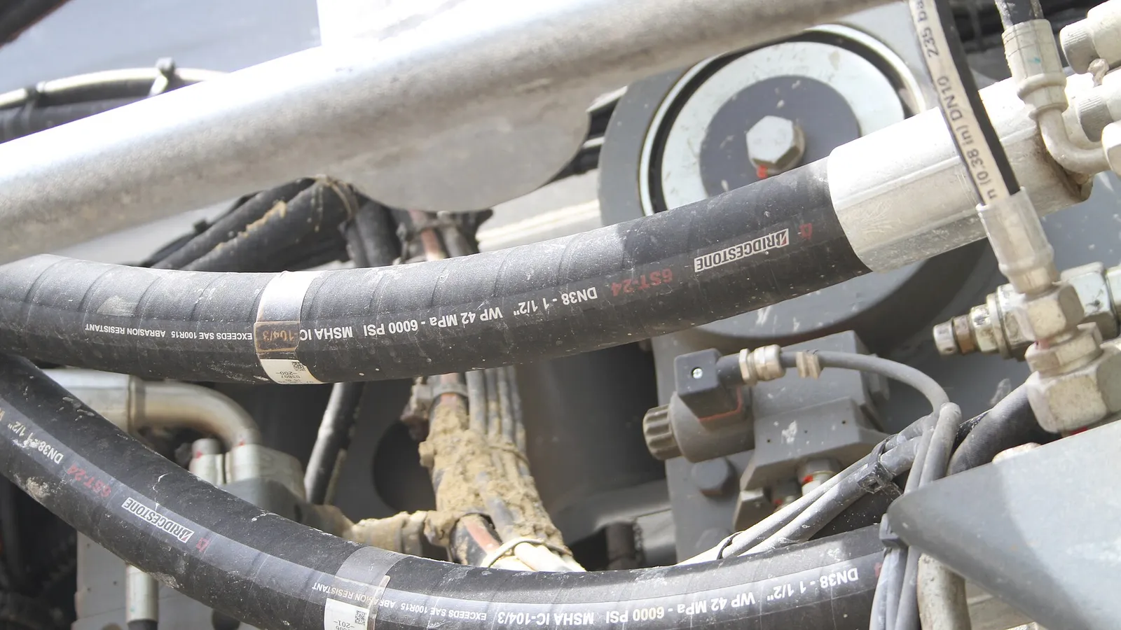
Hydraulic hose looks simple — a rubber tube with some wire around it — until a 6 mm hose rated for 4,000 bar-equivalent applications fails in a confined space and takes the whole line down with it. The engineering is in the layers: the inner tube that seals the fluid, the reinforcement that carries the pressure, and the cover that takes the abuse.
This guide decodes the specification system that governs hydraulic hose — the SAE 100R series and its EN equivalents — and walks through selection the way a fluid-power engineer actually does it: pressure, size, temperature, impulse life, and the failure modes that kill hoses early.
How a Hydraulic Hose Is Built
A hydraulic hose is three engineered layers working as one:
- Inner tube — oil-resistant synthetic rubber (typically NBR or HNBR), smooth enough to minimise pressure drop and carry the fluid without degradation
- Reinforcement — high-tensile steel wire, either braided (one or two layers) or spiral-wound (four or six layers for extreme pressure)
- Cover — weather-, oil- and abrasion-resistant rubber, often with a pinhole layer to vent the tube
The reinforcement is the identity of the hose: braid is flexible and cost-effective; spiral winding carries far higher pressure with better fatigue life, at the cost of stiffness.
The SAE 100R Series Decoded
The SAE 100R series is the global shorthand for hydraulic hose construction. Each “R” number defines a specific construction, pressure class and performance level — not a brand, not a diameter, a construction specification.
| Series | Construction | Typical working pressure (1/4“ size, indicative) | Typical use |
|---|---|---|---|
| 100R1AT | 1 wire braid | ~3,000 psi (210 bar) | General purpose, low-pressure circuits |
| 100R2AT | 2 wire braid | ~5,800 psi (400 bar) | Standard mobile & industrial duty |
| 100R3 | 2 textile braid | ~1,500 psi (100 bar) | Low-pressure, flexible applications |
| 100R4 | Spiral wire + textile | Vacuum to ~500 psi | Suction and return lines |
| 100R6 | 1 textile braid | ~500 psi (35 bar) | Very low pressure, compact |
| 100R7 | Thermoplastic, 1 braid | ~3,000 psi (210 bar) | Non-conductive, compact routing |
| 100R8 | Thermoplastic, 2 braid | ~5,000 psi (350 bar) | High-pressure thermoplastic |
| 100R12 | 4 spiral wire | ~4,000 psi (275 bar) | High-pressure, high-impulse |
| 100R13 | 6 spiral wire | ~5,000 psi (350 bar) | Extreme-pressure systems |
| 100R15 | 6 spiral wire | ~6,000 psi (415 bar) | Highest-pressure industrial |
Pressure values are indicative for the 1/4“ size class — the authoritative figures come from the manufacturer’s catalogue for the exact size, and from the governing standard.
EN equivalents you will see on European machines
- EN 853 1SN ≈ SAE 100R1AT
- EN 853 2SN ≈ SAE 100R2AT
- EN 857 1SC / 2SC — compact versions of 1SN/2SN with tighter bend radii
- EN 856 4SP / 4SH — spiral-wound high-pressure hoses
When a European machine specifies EN 856 4SH, substituting a braided hose is a safety downgrade — the reinforcement is different, not just the name.
Working Pressure: The 4:1 Rule
The single most important number on a hydraulic hose is working pressure — and it is defined conservatively. Standard hydraulic hose is designed with a 4:1 safety factor: minimum burst pressure is at least four times the maximum working pressure.
That means:
- A hose with 16,000 psi burst is rated for 4,000 psi working pressure
- The working pressure drops as hose size increases (larger diameters carry less pressure for the same reinforcement)
- Working pressure also drops with temperature and with certain fittings
Never run a hose at burst pressure, and never assume the number on the cover is burst pressure. The marking line gives both; the working figure is the one that governs design.
Pressure Drop and the Real System Limit
Selection is rarely about peak pressure alone. The system limit is often pressure drop — the friction of oil moving through the bore:
- Undersized hose = high fluid velocity, excessive pressure drop, heat generation
- Rule of thumb: keep flow velocity in pressure lines below ~15–20 ft/s (4.5–6 m/s), lower in return lines
- Oversizing adds cost, weight and routing difficulty for zero benefit
The correct process is: calculate the flow → size the bore for velocity → confirm the working pressure for that size → check bend radius and routing.
Temperature and Fluid Compatibility
Standard hydraulic hose handles −40 °C to +100 °C continuous service. Beyond that:
- HNBR tubes extend temperature and oil resistance for high-heat engine and industrial applications
- Thermoplastic hoses (R7/R8) offer different temperature and chemical windows, plus non-conductive options for aerial and utility equipment
- Fire-resistant covers (MSHA, EN 853 with FR cover) for mining and high-risk environments
The fluid matters as much as the temperature: phosphate esters (aviation and some industrial systems) attack standard NBR tubes — they need EPDM inner tubes. Check fluid compatibility against the tube compound before assuming a pressure rating is enough.
Pulse Life: The Test That Predicts Fatigue
A hydraulic system does not apply steady pressure — it pulses. The industry’s dynamic test is the impulse test: the hose is pressurised and released thousands of times at elevated temperature and a percentage of working pressure.
- SAE 100R series hoses are tested to defined impulse life (e.g. 100R2AT: 400,000+ cycles in the standard test)
- Spiral-wound hoses (R12/R13/R15) exist specifically because pulse fatigue, not static pressure, is what kills high-pressure systems
- Real-world pulse life depends on pressure spikes — transient peaks above working pressure that accumulate damage
If your system has pressure spikes (common with directional valves slamming closed), specify spiral-wound construction even if average pressure looks low.
Common Failure Modes and Their Causes
| Failure | Typical cause |
|---|---|
| Wire exposed at the cover | Abrasion against machine parts — cover wear, wrong routing |
| Inner tube collapse/swelling | Wrong tube compound for the fluid — compatibility failure |
| End fitting blow-off | Incorrect crimp, wrong fitting series, assembly error |
| Hose burst at a bend | Bend radius below minimum — reinforcement overstressed |
| External cracks | Ozone/UV exposure — wrong cover compound |
| Leak at coupling | Torque/crimp variation — assembly quality control |
The pattern: most hydraulic hose failures are selection or routing failures, not manufacturing failures. A hose correctly specified, correctly assembled and correctly routed outlives the machine it is on.
Five-Step Selection Process
Step 1 — Define the fluid. Oil type (mineral, phosphate ester, water-glycol) → picks the tube compound.
Step 2 — Define pressure. Maximum working pressure + spikes + safety factor → picks the reinforcement series.
Step 3 — Size the bore. Flow rate → velocity → bore size → confirm pressure for that size.
Step 4 — Check temperature and environment. Continuous temperature, ambient extremes, abrasion, UV, fire risk → picks the cover and tube grade.
Step 5 — Specify the assembly. Fittings series (SAE JIC, BSP, DIN 24°, flange), crimp spec, hose length with bend allowance → the complete assembly documentation.
Working Example: Sizing a Boom Line
A concrete example makes the process concrete. Take a mobile machine with a circuit flowing 40 L/min (10.6 US gpm) of mineral hydraulic oil at a working pressure of 210 bar (3,000 psi), ambient temperature up to 60 °C, with noticeable pressure spikes on valve closure.
Step 1 — fluid: mineral oil → NBR tube, standard.
Step 2 — bore sizing for velocity: target 4.5–6 m/s in pressure lines. For 40 L/min:
- 3/8“ (DN10) bore → ~8.8 m/s — too fast, excessive pressure drop and heat
- 1/2“ (DN13) bore → ~5 m/s — acceptable
- Select 1/2“ (DN13) as the starting size
Step 3 — pressure rating at that size: confirm the working pressure of the candidate series at 1/2“ size. A 2-wire braid (100R2AT / EN 853 2SN) 1/2“ hose is typically rated around 4,000 psi (275 bar) — comfortably above 210 bar.
Step 4 — spikes: pressure spikes on valve closure mean impulse life matters. 100R2AT is the standard answer for this duty class; if spikes exceed the working pressure repeatedly, step up to spiral-wound (R12 / EN 856).
Step 5 — routing and bend radius: with a minimum bend radius check against the actual routing path, and fittings per the machine’s port standard (below).
The result: 1/2“ EN 853 2SN (SAE 100R2AT) with the machine’s port-standard fittings — the industry-default answer for this exact duty, arrived at by calculation instead of guesswork.
Fitting Series Quick Reference
The hose is half the assembly; the fitting standard must match the machine’s ports. The four dominant global systems:
| System | Thread | Common markets | Typical pressure class |
|---|---|---|---|
| SAE JIC 37° | UNF flare | North America | High pressure |
| BSP (G / BSPP, BSPT) | British pipe | Europe, Asia, UK | Medium–high |
| DIN 24° (DKO/SAE-L) | Metric | Europe, China | High pressure |
| Flange (SAE 4-bolt / Code 61/62) | Flanged | Heavy mobile, industrial | Highest, large bore |
Common specification errors: mixing JIC and BSP fittings (they look similar, they are not compatible), using taper (BSPT) where parallel (BSPP) is specified, and flange codes mismatched between Code 61 and Code 62. When in doubt, match the fitting series to the machine’s existing ports and take a sample fitting to the supplier.
Installation and Routing Best Practice
Routing failures cause more premature hose failure than pressure miscalculation:
- Keep bend radius above minimum — never pull a hose tighter than its rated minimum bend radius; at fittings, allow a straight lead-in length before the bend (typically 6× OD)
- Avoid torsion — twisting the hose under pressure is a fast killer; rotate the fitting, not the hose
- Support long runs — clamps every 1–1.5 m prevent sag, abrasion and fatigue
- Keep away from heat sources and moving parts — use fire sleeves or shields where routing passes hot manifolds or exhausts
- Allow slack for movement — a hose connecting moving components needs length for flexing; too-tight routing concentrates flex at the fitting
- Label and document — each assembly with series, size, length, date and pressure rating makes maintenance and replacement traceable
Hydraulic Hose FAQ
Q: Can I replace a 2-wire braid with a 4-spiral hose of the same size? Pressure-wise often yes — but check the fitting series, bend radius and impulse requirements first. Spiral hose is stiffer; if the application needs flexibility, braid may be the better engineering choice despite the lower pressure headroom.
Q: What does the marking line on the hose mean? It encodes the standard, size, working pressure and often the manufacturer and date of manufacture. It is the identity card of the hose — read it before replacing, and keep it legible.
Q: How often should hydraulic hose be replaced? Depends on duty. High-impulse systems may need scheduled replacement; low-duty systems last years. Beyond visual inspection, track: cover condition, fitting tightness, stiffness changes, and impulse cycles for critical assemblies.
Q: What causes most hydraulic hose failures? Selection and routing errors — wrong tube for the fluid, undersized bore, tight bends, torsion, abrasion — outnumber manufacturing defects by a wide margin.
Q: Do you supply complete hydraulic assemblies? Yes — PureFlow supplies hydraulic hose assemblies crimped to the fitting series you specify, with pressure test documentation and batch traceability.
The Takeaway
Hydraulic hose is specified by construction standard, sized by flow, and rated by working pressure — with a 4:1 safety factor doing the quiet work underneath. Nail the fluid compatibility and the impulse reality of the system, and the hose becomes a fit-and-forget component instead of a maintenance line item.
If you are specifying hydraulic hose for a machine or a retrofit — send the fluid, peak pressure, flow, temperature and routing constraints — PureFlow will come back with the correct SAE series, size and assembly recommendation, factory-direct.
- Hydraulic Hose — the certified range
- Hose Assembly Guide — fittings, crimping and testing
- Chemical Transfer Hose Complete Guide — liner logic for non-petroleum fluids
- PTFE Hose Complete Guide — when chemical resistance meets high pressure